

The display has a location. The furniture is selected. The room looks finished on the plan. Then comes another question: where will the equipment, power connections, and cables go?
A clean display wall depends on more than what people see. The equipment location also needs a workable mounting arrangement, organized cable paths, proper ventilation, and access for changes. Planning those details early makes the wall box part of the design instead of a space to fill after the other decisions are made.
Start With an Equipment List
List every device that needs a home near the display, including media players, control hardware, network equipment, and power supplies. Record the actual dimensions and mounting requirements. Check where connectors sit and whether cables need to exit from the side, bottom, or rear of a device.
Use that list to establish the enclosure requirements. FSR's PWB-320 is designed for standard 4-inch wall construction and fits 16-inch on-center wood or steel stud bays. It provides an in-wall location for cable routing, AC connections, and digital media products. The fit within the wall is one part of the decision; the equipment layout within the box is another.
An enclosure behind a display also needs a realistic access plan. Consider the display mount and how you'll access the enclosure, rather than assuming a hidden box will remain easy to service.
Give Each Device a Defined Mounting Location
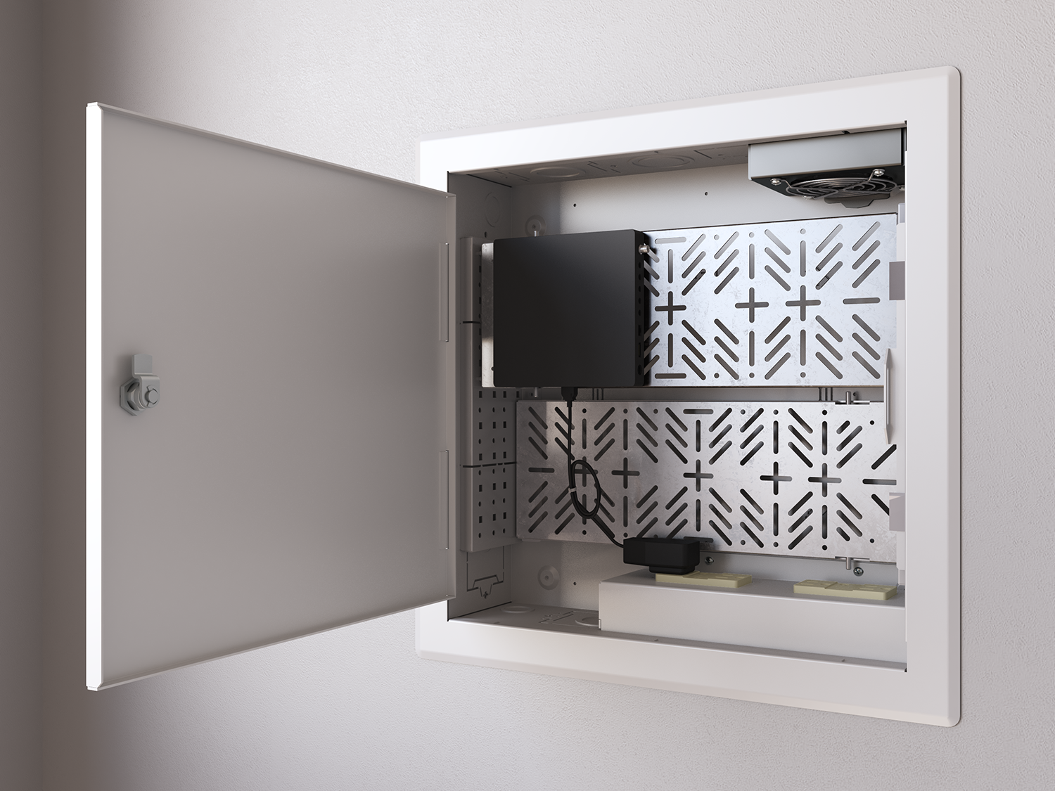
Plan where each device will be secured before concentrating on how much equipment can fit. A useful arrangement should give installers a clear way to mount components, connect them, and reach the parts most likely to need attention.
The PWB-320 includes flush cable-tie mounts, IPS mounting openings, and FSR's Triple Play mounting provisions. Optional adjustable equipment shelves provide another way to arrange components. You can adjust shelf position and depth, with horizontal or vertical mounting options to suit the equipment layout. Select shelves, covers, power accessories, and cooling with the appropriate box or kit.
For installations bringing multiple types of equipment together, FSR's MWB-28 wall box offers large and small internal mounting plates, a DIN-rail provision, and a cable raceway. Remove the small plate when using the DIN rail. These options support different mounting needs, but you still need to plan the arrangement around the actual devices.
Plan the Cable Paths Before Closing the Wall
A connection list is not the same thing as a cable-routing plan. Identify where each run enters the enclosure, how it reaches the device, and how you'll support the wiring. Consider access to connectors and the appearance of the completed installation.
FSR's PWB-320 Triple Play mounting solution offers options for conduit, box-less low-voltage plates, and standard single-gang low-voltage boxes. Its cable-tie mounts and IPS openings give installers defined places to organize connections, rather than relying on improvised arrangements behind the display.
The MWB-28 combines top and bottom knockouts with an internal wireway and included AC bracket. This makes cable entry and distribution part of the enclosure layout. In a multi-trade installation, agree on device locations and routing responsibilities before the wall is finished, and maintain the separation required for the selected systems.
Make Ventilation and Service Access Part of the Layout
Fitting the equipment into an enclosure is not the final test. Review each device's ventilation requirements and consider how the arrangement changes once cables and power supplies are installed. Leave the manufacturer's required clearances and avoid treating unused space as automatically available for another component.
FSR offers optional temperature-controlled cooling for the PWB-320 and an optional variable-speed, temperature-controlled fan for the MWB-28. These are configuration choices, not features to assume are included with every assembly. Select cooling based on the equipment and installation conditions, using the applicable product specifications.
Also picture a technician replacing one device. Can its connections be reached? Can the component be removed without dismantling unrelated equipment? A useful service plan starts with those practical questions, not just an open-door photograph.
Finish the Wall Without Hiding the Maintenance Plan
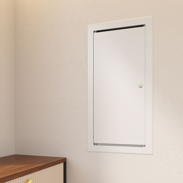
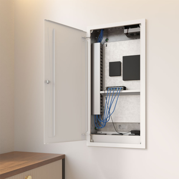
The enclosure's visible details should complement the room while preserving the access it needs. Consider the trim, door swing, lock, ventilation openings, and any cable exits alongside the wall finish and display position.
The PWB-320 offers trim and cover options, including a separately available locking hinged cover. The MWB-28 offers white cover options, keyed access, and a cover arrangement that can be oriented to suit access from the required side. Its back box and selected cover are ordered separately, so confirm the complete assembly.
Concealing equipment should not mean making it inaccessible. Whether the enclosure sits behind a display or in another suitable wall location, the finished installation should preserve a clear route for maintenance.
More Than a Place to Put Equipment
A wall box becomes more valuable when you select it around the equipment, cable routes, and people who will work with it. The PWB-320 and MWB-28 offer different ways to meet those requirements, from mounting display-related equipment to providing a shared location for multiple devices.